19 Nov 2017 Testing air-tec alternator
Just tested this Air-Tec alternator- worked like the others I have tested. http://www.airtecinc.us/aircraft.html
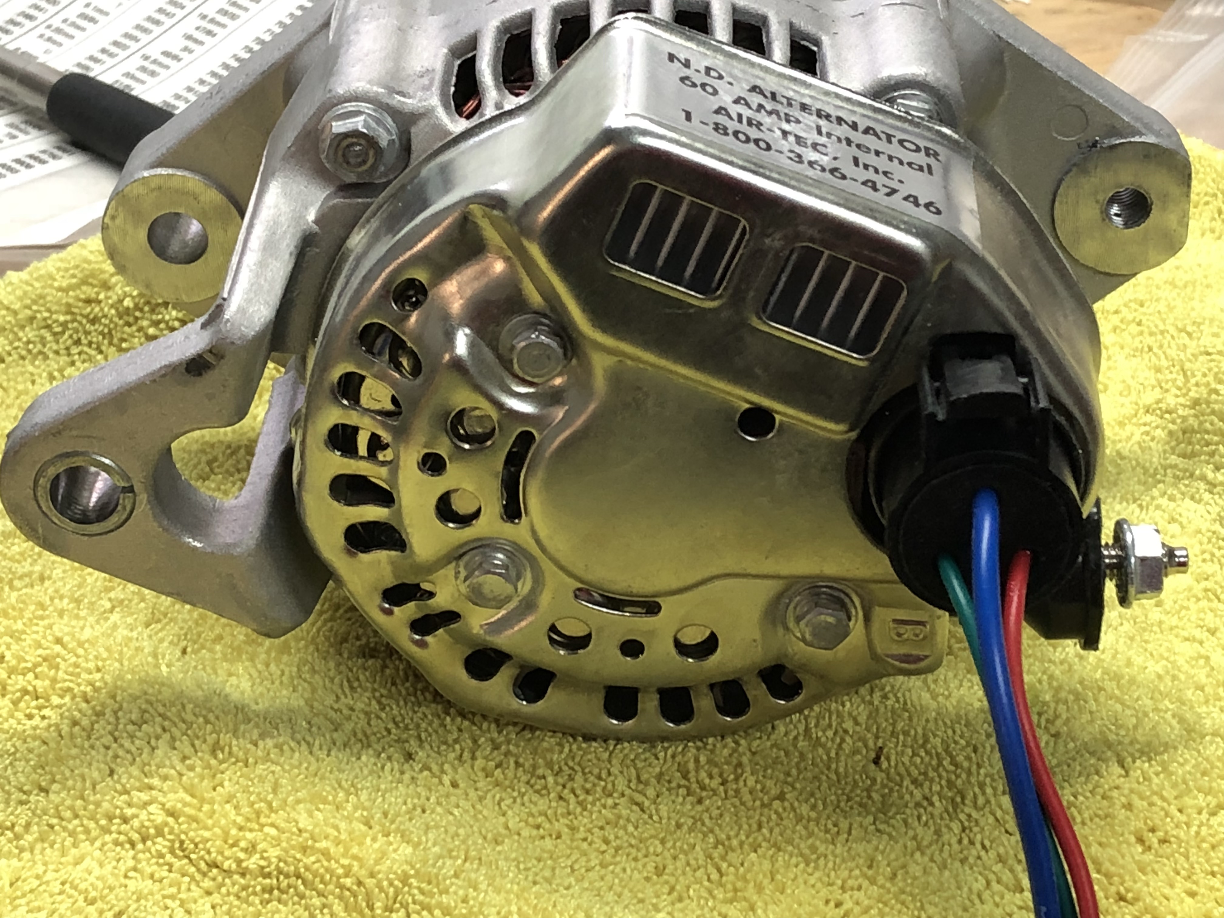
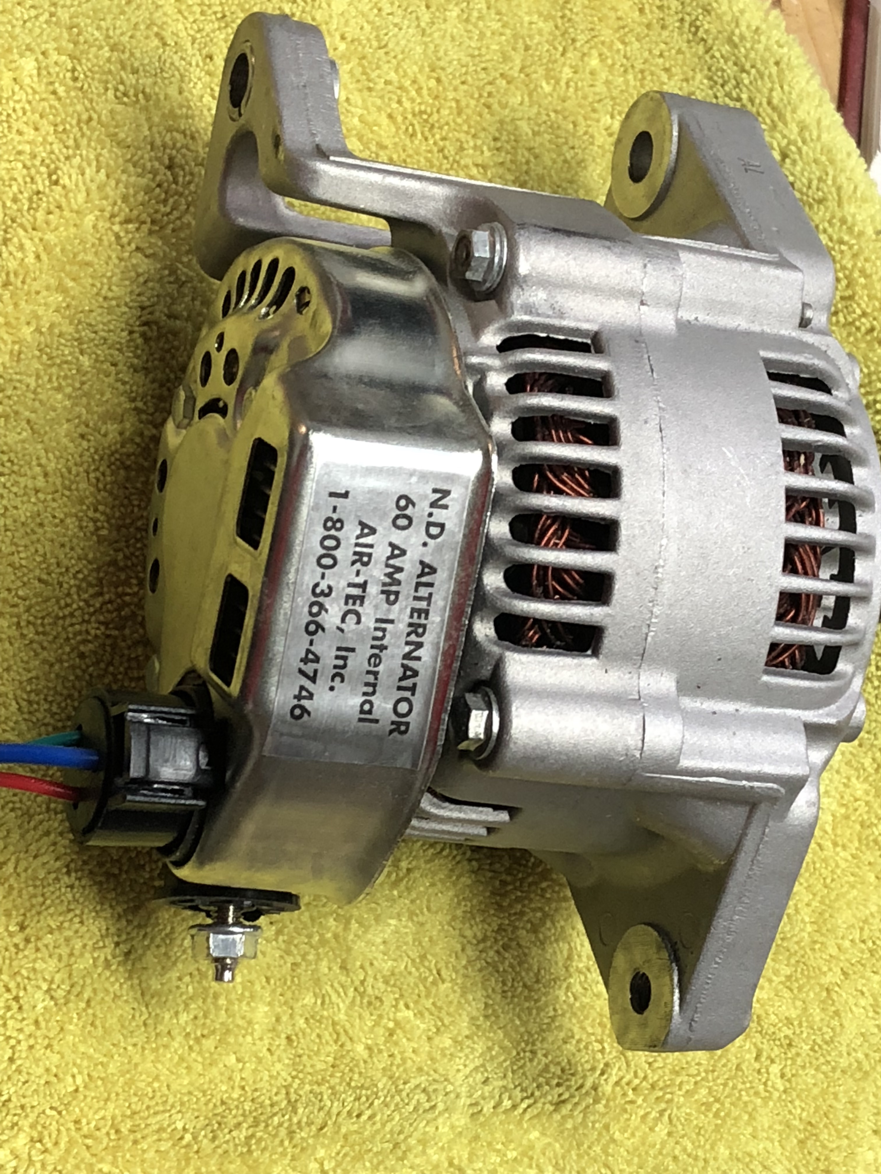
When the IG wire has 12v the alternator starts, and when I drop the 12v the alternator stops. It’s an internally regulated alternator. There are three wires – an ignition wire which starts and stops the alternator, a warning light wire, which is grounded when the alternator is not generating electrons (and possibly under other circumstances, I can’t be sure), and a Sense wire, which is a place where the voltage of the system should be sensed in order for the alternator to know how high of a voltage to send out. This is mainly used if the alternator is far from the battery, and allows for the voltage drop associated with long wiring runs to the battery.
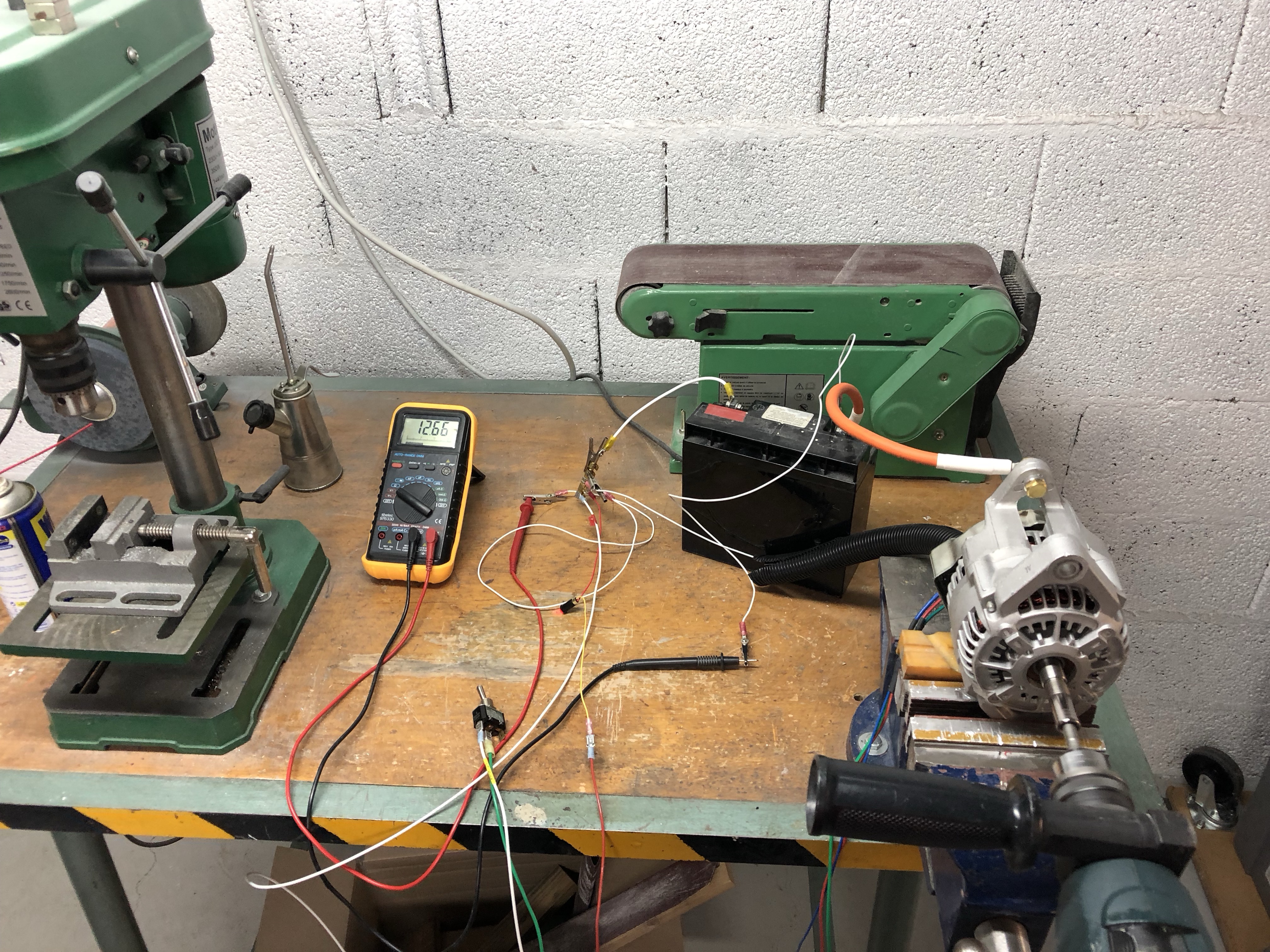
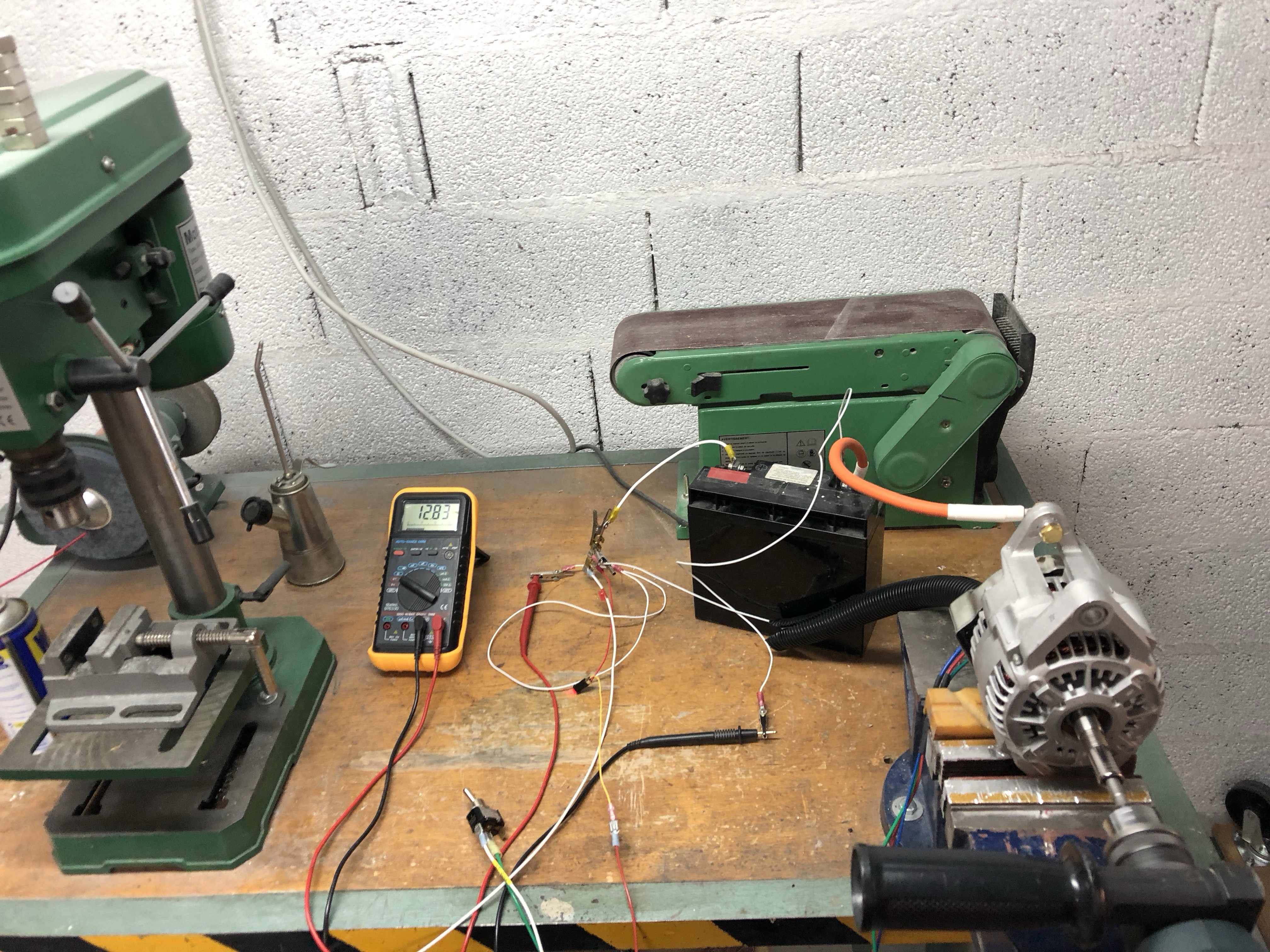
This is the test setup before turning on the alternator – note the voltage of the battery. The alternator is spinning freely.
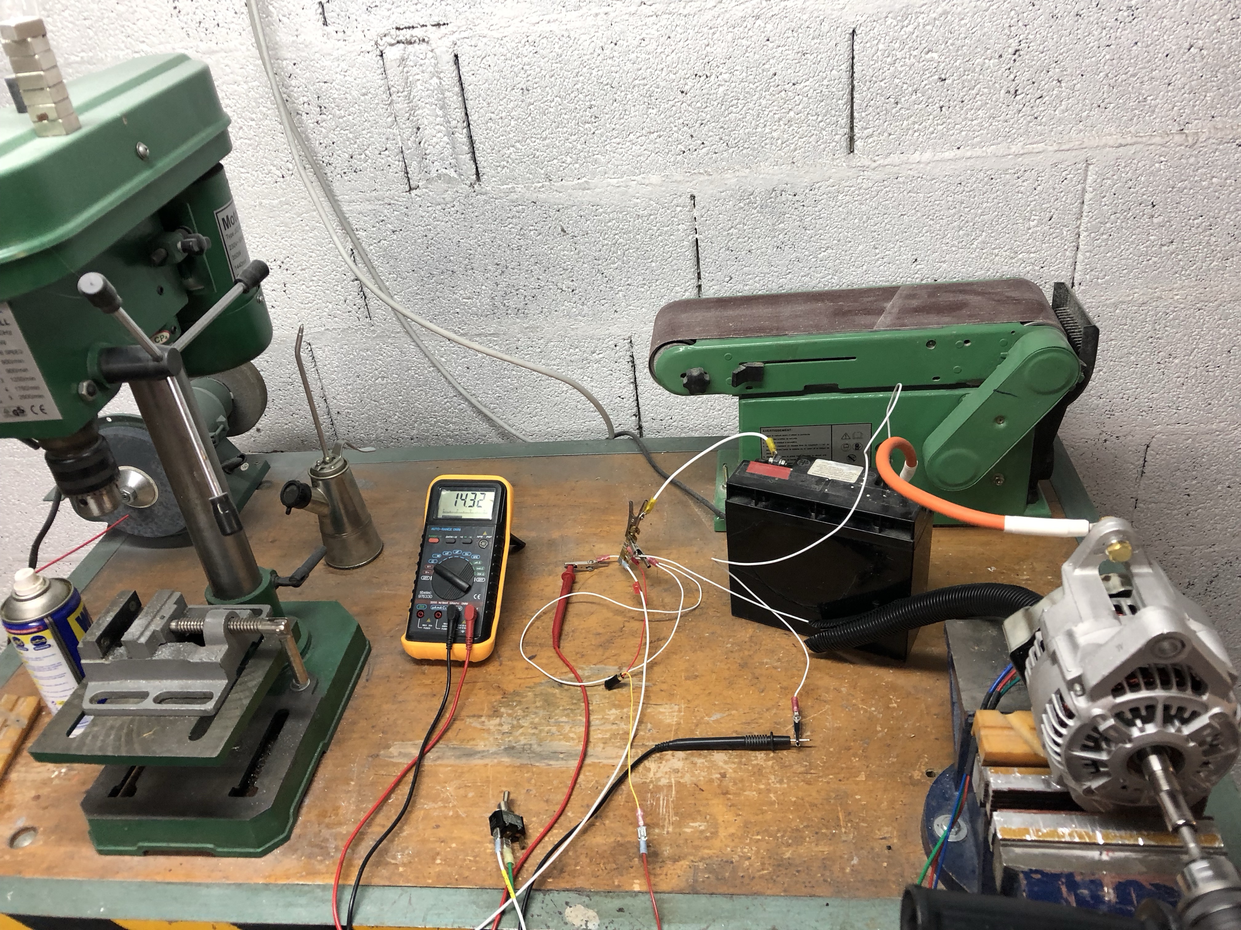
Now I turn on the 12v to the alternator, which increases the voltage, turns off the warning light, and causes resistance on the drill.
Still spinning the drill, I turn off the switch and the voltage drops, resistance drops, and the light comes on.
All worked as expected, but the things that I can’t test are, what happens if the internal voltage regulator has a massive failure? How will the alternator react when the 12v to the IG wire is removed? Just can’t know, which is why it’s a good idea to have some Over Voltage protection that will cut off the B lead in case of alternator overvoltage. This can be done with a crowbar connected to a contactor, or other methods of your choosing.
Be sure to visit http://www.aeroelectric.com/ and Van’s Airforce for more electrical information.
Sorry, the comment form is closed at this time.