23 May 2006 How does an alternator work?
This is one of the most lucid descriptions of how an alternator works that I have read. From one of the resident electricity wranglers on the AeroElectric Connection Matronics List, Brian “Brain” Lloyd.
If you go back to an elementary science class, someone once told you that if you wave a magnet around a wire, that wire will produce an electric current. They also probably told you that if you pass a current through a wire it will produce a magnetic field around the wire. This was the amazing discovery of Michael Faraday and upon which all electrical and radio theory is based.
Some alternators or generators do indeed use a permanent magnet whirling around inside a coil of wire to produce power but the output is directly proportional to how fast you spin it. If it makes more output than you need you must find a way to get rid of the excess. This is not a problem if the output is relatively small but if you want something that can produce a lot of output for the times when you need a lot of output, it produces way too much when you don’t need it all. Hence permanent magnet alternators, officially known as “dynamos”, tend to be small things.
But if you want one that can produce a lot of output when needed but not much output when not needed you need a way to vary the effectiveness. If you remember the two things that our buddy Mike discovered, i.e. that moving magnetism generates an electric current and moving electrons generate magnetism, you have the basic components you need. If you want to increase the output of your alternator at a given rotational velocity you need more magntism and vice versa. So how can we turn the magnatism up and down as needed? Why, we use a coil of wire with a current flowing through it. If we increase the current, the magnetism increases and the output of our alternator increases. If we reduce the current, the output of our alternator decreases. This electromagnet is the rotating part of the alternator. It is called the rotor but it is also called the field winding from the olden days when we used generators.
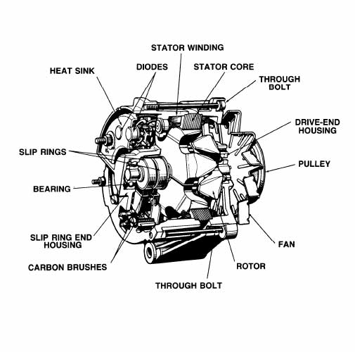
A generator has the power-producing windings on the spinning part called the armature and the magnetic field producing part, the field windings, around the outside. An alternator has the magnetic field windings on the spinning part (rotor) and the power-producing coils (stator) are around the outside. You see I keep using the term “magnetic field producing part” over again. That just got shortened over time to the word “field”.
So the way this whole thing works is to have an external sensor determine if the alternator is producing as much power as needed. It does this by measuring the voltage on the bus. If the voltage is too low it allows more current to flow through the field winding. This increases the magnetism in the center of the alternator and that then induces more output in the stator winding. The voltage rises. If the voltage gets higher than we want the VR reduces the current in the field, the magnetic field is decreased, the output of the stator windings is less, and the voltage at output is reduced. To me this represents PFM (Pure f’n magic) and is also PFN (pretty f’n neat). Thanks Mike!
Brian Lloyd
For more, check out Wikipedia’s Alternator entry: http://en.wikipedia.org/wiki/Alternator
Sorry, the comment form is closed at this time.