11 Sep 2004 EZ Pilot Autopilot servo installation
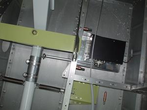
I decided to install the Trio Avionics EZ Pilot autopilot servo inside the fuselage, just under the pilot seat, on the left. Here is a view from the front.
Here are all the parts that I fabricated:
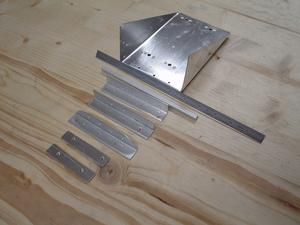
They include the bracket, three angles for the frame, two little offsets for the servo trim, and the pushrod. The pushrod is just a solid rod of 6mm aluminium. I drilled and tapped it for a 6-32 screw to allow the rod end bearings to go in there.
Forward angle length: 4.4″
Rear angle length: 4.3″ (shorter due to angle of the floor)
Pushrod length: 7″
Bottom angle length: 4.4″
Here is the completed bracket. Notice that I installed nutplates for 8-32 screws. This required me to drill out the little mounting tabs on the servo.
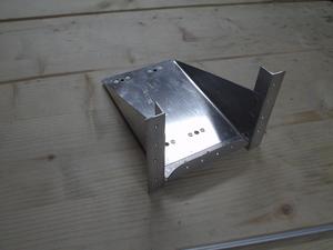
I still need to prime it, of course.
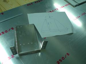
This took much longer than I had expected. I now understand the value of a pre-designed kit. For example, the idea for the autopilot servo bracket came from the trim servo bracket. Very similar design. The small details take a lot of time. The first time I built the bracket, I didn’t make the bracket long enough, which meant I could not remove the servo once the bracket was installed. The second time, the servo interfered with the rudder cable, so I had to lower it. As they say, third time’s a charm. Here are the dimensions of the third attempt. Note that I ended up cutting off the tabs, and riveting angle on there. This was to make it a bit stiffer.
One trick I learned from the Van’s trim servo kit is to make a “template” for drilling the holes in the floor spar. This was a big help.
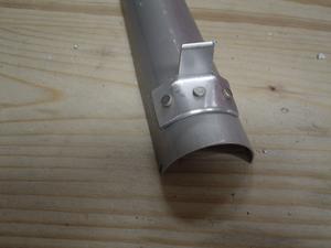
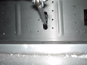
Here is the part that attaches to the control stick weldement. It’s half a piece of aluminium tube that I used for the elevator pushrod. I just chopped, bent, and riveted a piece of angle on there.
Here are some more view of the bracket installed, before riveting. Notice that the aluminium tube is taped and then attached with hose clamps. I’ll probably attach it with pop rivets once I take the weldement out when I paint the interior.
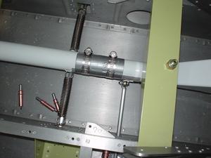
Notice that the brace has a slight angle from outboard to inboard. This was done to increase the distance between the bottom of the brace and the floor. When completely horizontal, it was a bit close to the floor, and I worried that it might touch if the servo causes a bit of motion. This should not happen, but just in case, I added a bit of space.
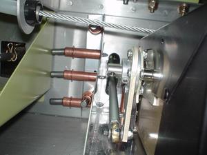
A view along the pushrod from outboard to inboard. Notice the trim servo bracket on the left (forward) of the autopilot servo. The autopilot servo actuating arm has almost 100% travel – The ailerons stop just before the trim servo arm stops touch. To get this I had to install the tab that attaches to the weldement at a slight angle towards the servo. This reduced the length of the arm the servo has to act on. Boy, that sounds ackward.
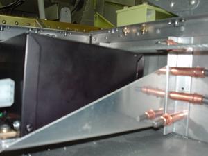
A view from the center of the fuselage looking out, left.
Continued in this article. http://www.rv8.ch/article.php?story=20041023174407440
Sorry, the comment form is closed at this time.